HOW-TO: Desolder & Remove Thru-Hole Component with Solder Wick
Note: This guide is based on the IPC 7711 3.1.5 standard. Purchase the full standard from the IPC organization. The graphics and text have been created to provide easy-to-use instructions. Any content that diverges or supplements the IPC standard with be noted on the graphics, and text will be blue.
This process is used to remove solder holding through-hole components. Desoldering is done from the underside, non-component side of the board.
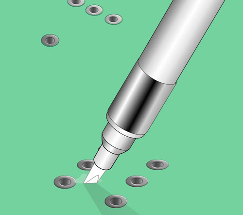
Step 1: Choose braid width and solder tip
|
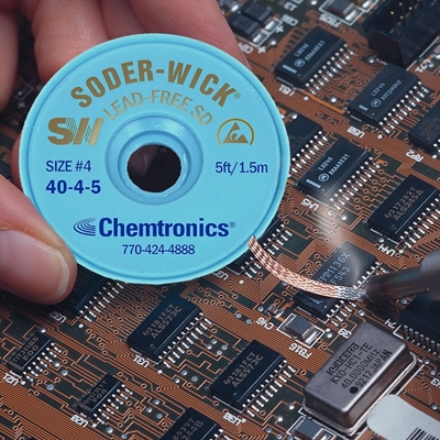
Select solder wick width.
Select solder tip size. |
Choose a width of braid that is approximately the width of the solder to be removed. Choose a solder tip with approximately the same width as the wick. Choose a desoldering braid that is coated with a flux that meets your requirements. Apply your own flux to unfluxed braid if use of a specific flux is required (not common). |
Step 2: Prepare iron
|
Clean solder tip. |
Select a temperature of approximately 315°C (599°F), and adjust as needed. Clean the solder tip. |
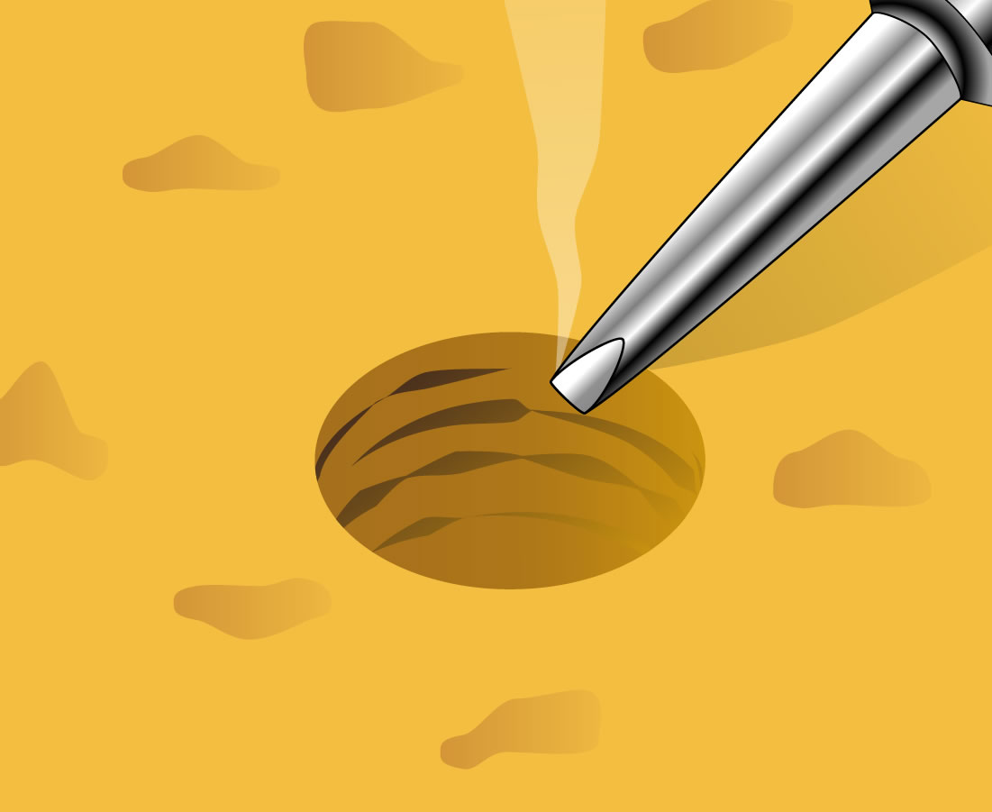
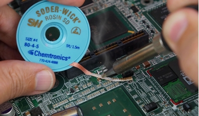
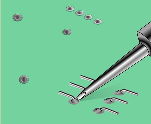
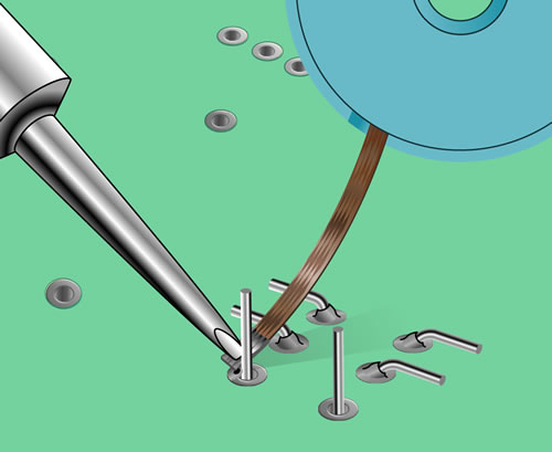
Step 3: Melt and Remove the solder
|
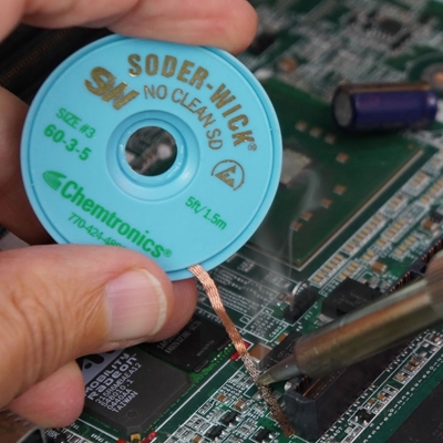
Remove solder from thru-hole lead. |
Place braid over the lead land junction. Place the iron tip on the braid directly over the solder to be removed. Allow heat to conduct through the braid to melt the solder. The braid will absorb solder using a wicking action. Use caution holding the braid, as heat will also travel through the braid. Additional flux may be added to the solder area or to the braid if wicking action is inadequate. |
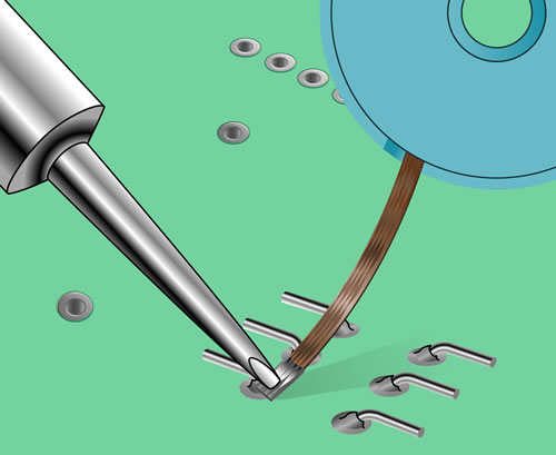
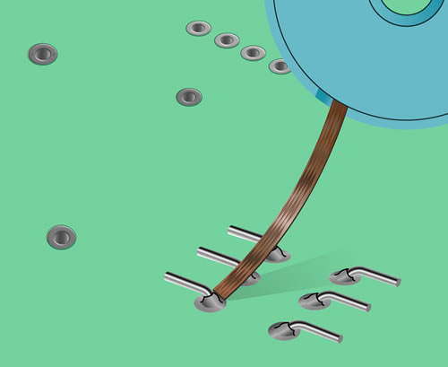
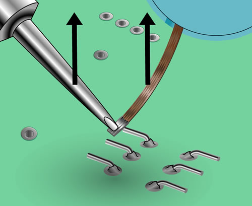
Step 4: Remove the Braid
|
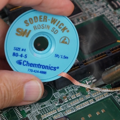
Lift solder wick and tip. |
Remove soldering iron and the braid at the same time immediately when wicking action has ceased. Applying heat for too long can increase the chance of damaging the land. Trim away used areas of the braid. |
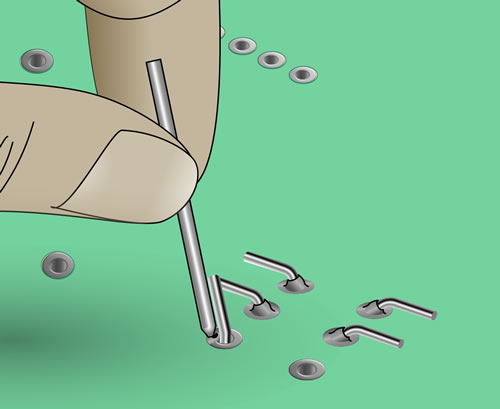
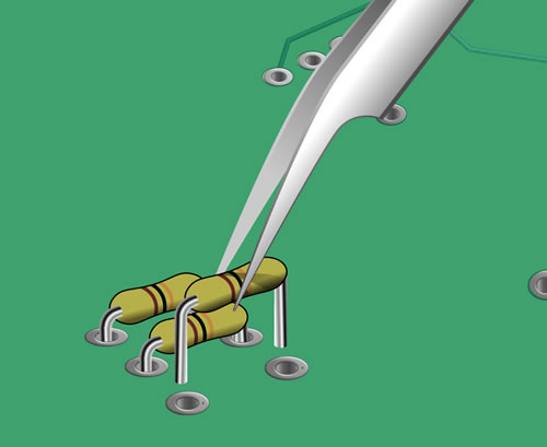
Step 5: Remove the Component
|
Straighten lead.
Remove solder for exposed side of lead.
Remove component. |
If necessary for a clenched lead, bend the lead to a vertical position to allow for component removal. Repeat the process to remove solder from additional connections. Skip and alternate connections to avoid applying excess heat on multileaded devices with close leads. Apply more solder and repeat the desoldering process in cases where there is a small amount of unreachable solder that is holding a lead in place. |
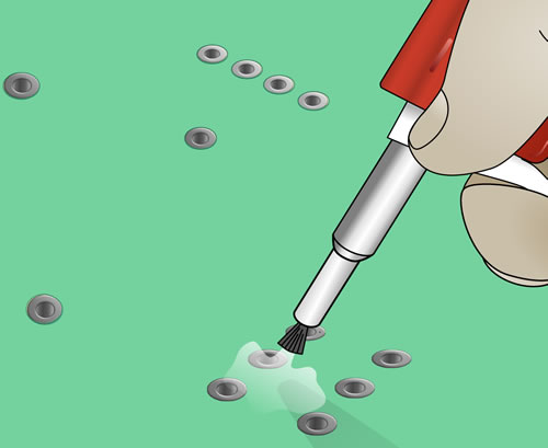
Step 6: Clean.
|
Remove flux residue.
|
Clean and inspect area. |
Tools & Materials
-
Cleaner like flux remover pen or aerosol flux remover
-
Soldering iron with tips
-
Solder sponge or brass tip cleaner
- Tweezers
Ask A Technical Question
Stay up-to-date on Chemtronics news, products, videos & more.
Related Products