Halo Effect on Fiber Optic End Faces: Cause and Prevention
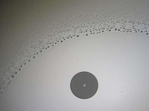
Haloing is a contamination defect that appears on fiber optic end face connections. If present, using a fiberscope to inspect an end face will reveal a discolored ring usually midway between the fiber core and the leading edge of the chamfer. There is some debate about the necessity of removing the halo, since it is not typically visible on the fiber optic core. Some discount its impact on transmission. However, those responsible for trouble-free installation or maintenance of fiber optic networks, higher power networks are more concerned about the potential loss in signal quality and potential serious damage from the halo. Their concern extends beyond the visible halo to other less visible or invisible contamination on the core and on potential migration of halo soils into the core. Whether or not it distorts or impedes a signal may be debatable but the presence of the halo definitely indicates a failure of the end face cleaning process.
The appearance of halos suggests that halos are composed of a mixed variety of substances, such as very small particulates, as well as substances that are soluble and semi-soluble in cleaning solvents. Understanding the origins of the contaminants would help describe specifically their composition. The potential sources are quite varied, (1) handling oils and salts from workers hands, (2) airborne soils, especially particles (3) impurities in the cleaning solvent from any surface the cleaning solvent has contacted before being applied to the end face, (4) cross-contamination from other connectors, (5) buffer gels, (6) cellulose wipes (cotton and paper tissues) and (7) any trace machining and processing fluids from the connector components such as plasticizers from dust cap plastics. Understanding halo composition would also help determine the best method for removing and preventing them.
Current observations indicate that the halo effect appears to occur most often with the use of IPA (isopropanol or isopropyl alcohol). This seems especially true when excess amounts of IPA are used. Excess quantities of other solvents are also observed to be likely causes of halos.
The halo pattern is quite consistent with a surface tension and surface affinity phenomenon analogous to capillary effects where a liquid is held in a crevice or drawn up a tube. A liquid will tend to minimize its exposed surface area and will crawl into crevices (capillaries) as deeply as possible in an attempt to wet the capillary surfaces and minimize its own surface area exposure to the ambient environment.
Capillary Effect
Capillary action, capillary effect, capillarity or capillary motion is the ability of a solid surface to draw a liquid upwards against the force of gravity. One typical example is a xylem tube in a plant which conducts water up its stem. The effects can also be seen readily with porous paper or a lantern wick. It occurs when the adhesive intermolecular forces (affinity) between the liquid and a solid are stronger than the cohesive intermolecular forces within the liquid. The effect causes a concave meniscus to form where the liquid is in contact with a vertical surface. The same effect is what causes porous materials to absorb liquids.
A common apparatus used to demonstrate capillary action is the capillary tube. When the lower end of a vertical glass tube is placed in a liquid such as water, a concave meniscus forms. Surface tension pulls the liquid column up until there is a sufficient weight of liquid for gravitational forces to overcome the intermolecular forces. The weight of the liquid column is proportional to the square of the tube's diameter, but the contact area between the liquid and the tube is proportional only to the diameter of the tube, so a narrow tube or thin crevice will draw a liquid column higher than a wide tube. For example, theoretically a glass capillary tube 0.5 mm in diameter will lift a 2.8 cm column of water.
Fiber Optic End Face Halo Creation
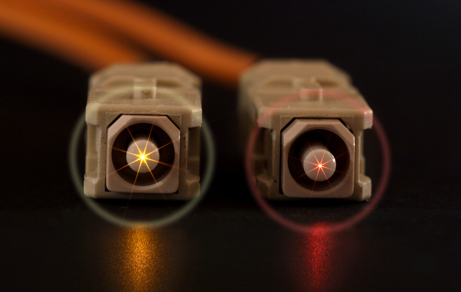
When two fiber optic end faces are mated, the convex curve of the end face creates circular crevice appearing as a ring shaped gap that is wider on the outside (farther from the core) and that tapers to a point toward the core where the ceramic ferrule end faces actually make contact. A cross-section of this ring would appear as a wedge.
Liquid will be drawn from the surfaces inside this connection to the tightest area, the wedge-like, circular crevice, which could be referred to as the halo zone. However, it cannot penetrate deeper because the end faces squeeze it back out. The surface tension of the liquid dictates how deeply it will penetrate the crevice. A high surface tension liquid like pure water will not wet these surfaces unless it has a specific affinity for the surface and lowers the overall surface tension of the system. The surface tension of the substrate must be higher than the surface tension of the liquid for the capillary effect to occur. This is why pure water tends to bead on waterproof fabrics (low surface tension substrate, low water affinity), yet, water will be quickly drawn into other fabrics like cotton (high surface tension substrate, high water affinity).
The liquid causing the halo is probably a mixture of residual IPA, condensed atmospheric water, water from IPA solvent and various contaminants such as airborne particles, traces of machining and lubricating oils, handling soils and solvent impurities. The surface tension of the liquid in this halo will be well below water because IPA and contaminants lower water surface tension quite efficiently. The affinity and bonds between glass and IPA/water and between most ceramics and IPA/water is quite strong and draw the soiled solvent into the circular crevice.
The contaminants making up the halo are present when the end faces are mated. The capillary effect explains why the contaminants are not seen when inspected even though they are there before mating. The contaminants are in a thin transparent, dissolved film spread evenly across the end face because no capillary exists before mating. They may also be in crevices and surfaces not subject to fiberscope inspection such between the alignment sleeve and ferrule. Mating the end faces forms the capillary and consequently draws the liquid into the halo. The liquid (IPA/water mix) evaporates and contaminants are left behind in the halo shaped film on the end face.
Halo formation can also be considered in terms of counterbalancing two forces; the force produced by the mating the end face surfaces, that squeezes the contaminants out and away from the center of the end faces, and the capillary force produced by the creation of the halo zone, that tries to draw the contaminants in toward the center of the end face.
Much of the blame for halo formation can be attributed to use and especially excessive use of IPA. It tends to be a slower evaporator and therefore more likely to be trapped in a connector when it is mated. Because it is hygroscopic even high purity IPA will eventually attract water and other impurities. Therefore, IPA also tends to have a high water content, which further slows its evaporation rate. Also, IPA is a poor solvent for many common soils such as buffer gels and oils. Consequently, it does not fully dissolve them and leaves a larger portion of those contaminants on the end face surface.
The way IPA is used is a major contributing factor. It is usually packaged and stored poorly and handled casually which raises its chances of being contaminated. When used, it is usually applied with a saturated wipe or directly to an end face surface in excessive quantities (in part because it does not work well for all soils). This excess liquid penetrates all areas of the connector and becomes very difficult to remove. Contaminants stay with the liquid so, the liquid must be removed or it will simply re-deposit the soils. Furthermore, a wipe or swab that is saturated or oversaturated with IPA will not absorb the used, soiled IPA from the surface. IPA itself may not actually cause halos every time it is used but it certainly does create the conditions under which haloing occurs.
Fiber Optic End Face Halo Prevention
The most important consideration in preventing halo formation is removing all the residual contaminated liquid cleaning solvent from the surface after it has lifted the contamination from the end face. Contamination almost always stays with the liquid, so, if all the residual contaminated liquid cleaning solvent is not removed, then the contaminants will simply be re-deposited when it evaporates.
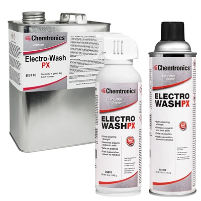
A cleaning solvent with broad solubility, low alcohol content and fast evaporation rate is required to prevent haloing. With these properties, a solvent will (a) remove all contamination using minimal quantities, (b) not attract water to the surface and (c) not lurk in inaccessible crevices deep in connectors. Chemtronics’ Electro-Wash® PX is an ideal precision solvent blend engineered for this propose. In addition to being an excellent solvent blend for the soils being removed, it is processed and packaged to eliminate the chances for contamination. Electro-Wash® PX is made with pure solvents, blended under controlled conditions and micron-filtered when filled. Also, because Electro-Wash® PX is an aerosol, no air, moisture or contamination is drawn back into the container when the cleaning solvent is delivered. The first drop and the last drop of Electro-Wash PX is the same quality formulation.
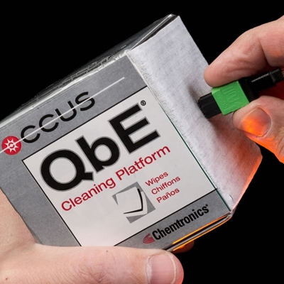
The next feature required to prevent haloing and deliver a clean connection is the wipe and how it is used. Lint-free synthetic or synthetic blends engineered and manufactured for industrial cleanrooms are ideal. Such wipes, found in the QbE® wiping tool, are made with clean materials that are processed and packaged under clean conditions.
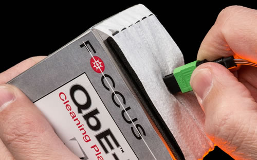
The method prescribed by Chemtronics is the Combination Cleaning Process, which is a wet-to-dry technique, using a QbE wiping tool. To use it properly, a small coin size (nickel or quarter) drop of Electro-Wash PX solvent is applied to a corner of the wipe while the wipe rests on the soft platen work surface attached to the QbE box. Then the end face is swiped 3 times from the wet spot into the dry portion of the wipe in a single smooth continuous stroke. The technique is very simple and easy to perform but complex cleaning actions are taking place. When the end face is touched to the wet spot on the wipe, the solvent dissolves soluble soils and lifts insoluble particles from the end face. As the end face glides across the solvent spot, soils and particles are absorbed by the wipe and fresh solvent is applied to the end face removing more soils. Then, as the end face continues to glide into the dry portion of the wipe all remaining soiled solvent is drawn into the dry fibers leaving a dry, pristine, clean end face.
If it is necessary to clean an end face mounted in a backplane, a swab is used. Swabs for 2.5mm, 1.25mm and MTP connectors are all available from Chemtronics. The technique also employs a wet-to-dry technique and a minimal amount of the Electro-Wash® PX engineered solvent formulation. The same coin sized spot is applied to a QbE wipe then an appropriately sized swab is touched to the spot for 5 to 10 seconds. The dampened swab is then inserted into the connector and twisted (LC and SC connectors) or swiped (MTP connector). This technique will moderate the amount of solvent used to clean the end face. This application is especially susceptible to problems from excess solvent due to the difficulty in removing soiled solvent from a female connection. Consequently, it is especially important to avoid excess use of solvent in this procedure. All the solvent introduced to the end face to clean must be removed other wise, it will simply redeposit the soil when it evaporates. This procedure is usually sufficient but following a dampened swab with a dry swab will ensure a dry, pristine, clean end face.
The halo effect is a ring of contamination on an end face created by surface tension and capillary effects. It is caused by the use, overuse and misuse of solvents (especially isopropyl alcohol) and saturated wipes, which loosens contamination but does not always remove all contamination from the end face. The halo can be eliminate and prevented with a system from Chemtronics that employs a technique known as the Combination Cleaning Process, which uses a precision, engineered cleaning solvent blend known as Electro-Wash PX and uses a patented, easy to use wiping tool known as a QbE.
For more information, contact your Chemtronics application specialist at 678-928-6534 or [email protected].
Ask A Technical Question
Stay up-to-date on Chemtronics news, products, videos & more.
Related Products