Drawing Conductive Traces: Fast & Effective Method of Repairing PCB Trace Defects
Continuity of copper traces is one of the primary tests conducted in a Printed Circuit Board (PCB) before qualifying. Any broken or damaged trace, sooner or later, may pose a risk to normal circuit operation. Hence, repairing these traces becomes inevitable for ensuring circuit reliability.
Moreover, in some PCBs, the reworking of traces require methods other than the conventional methods of jumper and solder tracing. Particularly, flexible PCBs and electrochromic devices are susceptible to high temperature of soldering. Any attempt to raise temperature beyond 100oC, may cause permanent damage to these circuits.
The PCB engineer must come up with alternative ideas for reworking these delicate circuits while not compromising the circuit performance.
This article highlights methods to rework damaged PCB traces. The article next discusses the new developments in the field of PCB reworking. Particularly, the pros and cons of using conductive pens are discussed. To educate the readers, the article mentions some case studies supporting new methods of PCB reworking.
Finally, some products from Chemtronics are highlighted to aid the PCB engineers and technicians in overcoming these new challenges.
How to Effectively Rework Damaged Traces?
Besides production faults, numerous causes of trace damage include short circuit, lightning, overheating, wear, and tear. Similarly, numerous methods also exist to fix these traces. Perhaps the most common method is to solder a jumper to restore continuity.
For a detailed explanation how to repair a damaged trace with a wire jumper, check out “HOW-TO: PCB Trace Repair With a Wire Jumper”.
Though this method is simple and may provide a mechanically strong connection, it requires exposing the PCB to high soldering temperatures. This temperature may harm some temperature-sensitive components nearby or the PCB itself (e.g., flexible PCBs, electrochromic devices [1], or PCBs involving displays).
If enameled wire is used as a jumper, the elevated temperature may remove its insulation. Moreover, this method may prove to be time-consuming if there is a batch of PCBs with the same issue. Additionally, it can result in unattractive PCBs.
Another way of reworking is to solder trace the damaged part. This again requires maintaining high soldering temperatures, which may be detrimental in some cases.
For more details on this PCB repair process, go to “HOW-TO: PCB Trace Repair Using Foil Jumper & Epoxy Overcoat”.
Recent trends of manufacturing flexible, biodegradable, and recyclable electronics have led electronics manufacturers to explore the possibility of hand-drawn PCB traces [2]. Conductive inks have made this task achievable. Not only are these conductive inks useful in prototyping, they are equally practical in reworking any damaged PCB traces.
For more details on drawing conductive trace repairs, go to “HOW-TO: PCB Trace Repair With Conductive Ink”.
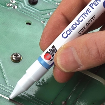
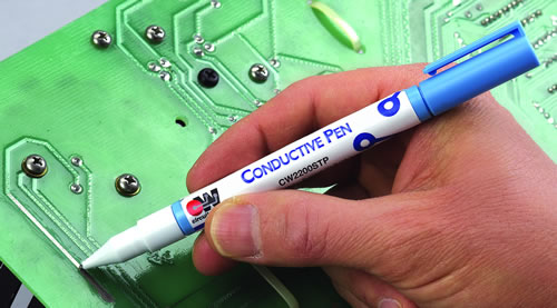
Conductive Pens for Drawing Traces
During the last decade, Silver- and Nickel-based conductive pens gained popularity among electronics professionals. Because of its excellent conductivity, stability, and high-volume manufacturability, Silver remains the preferred option in printed electronics [3].
Besides prototyping, these conductive pens offer quick and easy rework of damaged traces without exposing the PCB to high temperatures. One can literally redraw the traces using these pens. The Nickel and Silver traces take minutes to dry at room temperature. Moreover, Nickel- or Silver-based acrylic polymers are excellent alternatives to solder printing.
Though these conductive pens are a good choice for electronics repairing, they have some inherent limitations as well. One major limitation is the large size (in μm) of Silver particles that limit the minimum width of the trace to 1 mm.
Moreover, the traces remain brittle. With most conductive pens, it can be challenging to repair flexible circuit designs in this way [4]. To overcome this issue, Chemtronics offers their CircuitWorks Flex Conductive Pen (part #CW2900).
For the ink, silver is the most common conductive material because of the high conductivity, but Nickel may be the preferred choice due to lower cost.
The two materials do offer different performance in regards to temperature, resistance, and current carrying capability, as a case study illustrates.
Performance Analysis of Conductive Pens
Resistance Measurement
In "Investigation on Current Capabilities of Ni–Based Conductive Pastes for PCB repair"[5], a research study analyzes the resistance offered and current carrying capability of Nickel traces.
PCB patterns of varying widths and gaps, designed in CAD, are printed on different substrates (FR4, FR2). The test patterns are depicted in Figure 1. Trace widths of 0.8 mm, 1 mm, and 1.5 mm while trace gaps of 0.5 mm and 1 mm are used as test cases.
To ensure continuity, Nickel-based conductive paste was used to fill the gap in the copper traces. Measuring resistance of Nickel ink joint using digital multimeter produced results in the range of 0.2 – 3 Ω, depicted in Figure 2. The graph clearly shows that the wider PCB traces exhibit less resistance.
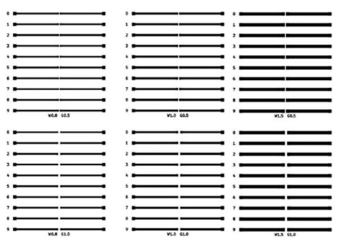
Figure 1: PCB trace patterns with varying parameters [5]
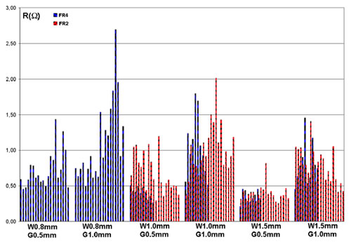
Figure 2: Resistance measurement with varying trace parameters – Nickel-based paste [5]
Similar experiments using Silver-based conductive paste is carried out in [6]. The results in Figure 3 suggest that Silver may be a superior choice for trace reworking considering its lower resistance.
Maximum trace resistance is 0.3 Ω while most tracks have resistances below 0.15 Ω. FR4 substrate depicts most promising results. Compared to Silver, the average resistance and the dispersion in resistance values of Nickel reworked traces are considerably larger.
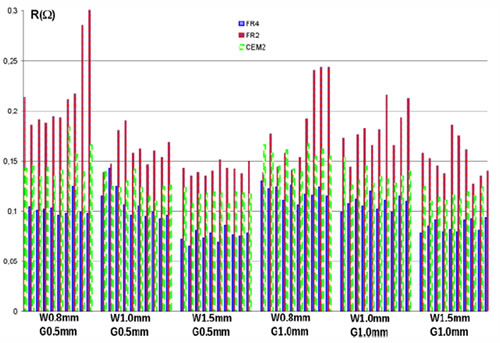
Figure 3: Resistance measurement with varying trace parameters – Silver-based paste [6]
Current Capability
The results in "Investigation on Current Capabilities of Ni–Based Conductive Pastes for PCB repair"[5] indicate that Nickel-based conductive ink performs without degradation for low currents in the range 0 – 200 mA. Beyond this limit, the trace resistance starts varying which indicates trace burning has started.
This limit can be increased slightly by increasing the trace width. Contrary to Nickel, Silver-based conductive inks demonstrate greater current carrying capacity. For a FR4 board with 1 mm trace width and 1 mm trace gap, no considerable resistance changes were noted until current was raised to 6 A.
However, at 10 A, the resistance value started increasing after almost 5 minutes of testing. The increasing resistance indicates that the trace will be burnt if this value of current persists. Figure 4 summarizes the current carrying performance of Silver-based ink on FR4 substrate.
The results on FR2 and CEM substrates are also promising, though they are not shown in this article. Overall, the conclusion from this study is that traces repaired with Silver-based conductive ink can withstand currents in the range 1 – 3A for long periods without any degradation in performance. The reader must keep in mind that the conductive inks (both Nickel and Silver) on the traces were applied using pens.
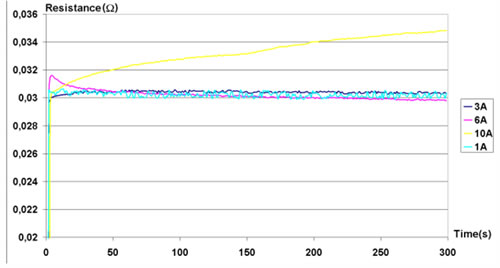
Figure 4: FR4 Resistance measurement corresponding to varying current values – Silver-based paste [6]
Thermal Performance
Temperature serves as a Key Performance Indicator in evaluating the capability of repaired traces to withstand large currents for longer durations. In "Analysis of Current Carrying Capacity of Silver based conductive pastes for PCB repair"[6], a case study attempts to evaluate the thermal performance of repaired (with Silver ink) traces with the aid of infrared camera.
At a trace current of 6A on a FR4 substrate, the temperature of Silver ink was found equal to or less than the surrounding copper areas. With the camera focused on Silver trace, Figure 5 elaborates this result.
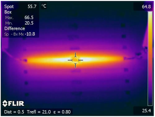
Figure 5: Thermal testing of repaired trace - Silver paste [6]
Figure 6 portrays the graphical summary of the thermal performance of repaired traces. The results indicate that within the current range 1 – 3A, the temperature increase is modest, and therefore it is safe to use Silver paste in this range. The Silver paste is able to withstand current of up to 6 A as well, but for short time periods only [6]. It is not safe to use Silver paste for longer durations if current exceeds 3A, because the trace will start burning.
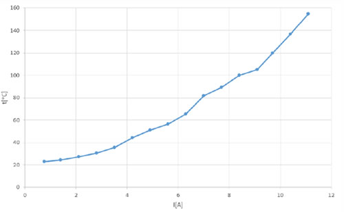
Figure 6: Current vs temperature graph of repaired trace - SIlver paste [6]
CircuitWorks Conductive Pens
The results from literature suggest that the choice between Silver and Nickel conductive inks depends on the final application. For lower current applications, CircuitWorks Nickel Conductive Pen (CW3000) is an economical option.
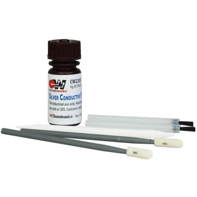
Silver-based conductive pens offer superior performance as the current increases. With a conductivity range of 0.02-0.05 ohms/sq/mil, CircuitWorks Silver Conductive Pen is the most favorable option. For finer traces, its micro tip variant (CW2200MTP) is an ideal choice. Conductive Paint (CW2205) is also available for either very fine work applied with a pick, or larger areas (e.g., shielding repair) with a brush or swab. The repaired traces take 20 minutes to dry at room temperature (25oC). Maximum operating temperature for this product is 205oC.
Silver Flex Conductive Pen (CW2900) is engineered specially for flexible PCBs and so it’s maximum operating temperature is limited to 100oC. To get started, the article on Conductive Pen Tips and Tricks for Best Performance may assist engineers or technicians working on PCBs.
For more information or technical support, contact Chemtronics at [email protected] or 678-928-5845.
References
|
[1] |
R. A. D. Ciprian Ionescu, "Performance studies of electrochromic displays," in Advanced Topics in Optoelectronics, Microelectronics, and Nanotechnologies VII, Constanta, 2015. |
|
[2] |
A. W. A. P. M. N. a. N. M. Júlio C. Costa, "Hand-Drawn Resistors, Capacitors, Diodes, and Circuits for a Pressure Sensor System on Paper," Advanced Electronic Materials, vol. 4, no. 5, 2018. |
|
[3] |
J. R. D. D. K. K. A. Scott E. Gordon, "Advances in Conductive Inks across Multiple Applications and Deposition Platforms," in APEX EXPO, 2012. |
|
[4] |
S. H. B. S. C. C. Z. Yoshihiro Kawahara, "Instant Inkjet Circuits: Lab-Based Inkjet Printing To Support Rapid Prototyping of UbiComp Devices," in Proceedings of the 2013 ACM international joint conference on Pervasive and ubiquitous computing, 2013. |
|
[5] |
A. D. B. T. M. Cristina I. Marghescu, "Investigation on Current Capabilities of Ni–Based Conductive Pastes for PCB repair," in 2015 38th International Spring Seminar on Electronics Technology (ISSE), Eger, 2015. |
|
[6] |
C. I. M. Andrei Drumea, "Analysis of Current Carrying Capacity of Silver based conductive pastes for PCB repair," in 2015 IEEE 21st International Symposium for Design and Technology in Electronic Packaging (SIITME), Brasov, 2015. |
Ask A Technical Question
Stay up-to-date on Chemtronics news, products, videos & more.
Related Products