HOW-TO: PCB Trace Repair Using Adhesive-backed Foil Jumper
Note: This guide is based on the IPC 7721 4.2.2 standard. Purchase the full standard from the IPC organization. The graphics and text have been created to provide easy-to-use instructions. Any content that diverges or supplements the IPC standard with be noted on the graphics, and text will be blue.
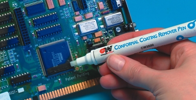
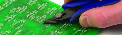
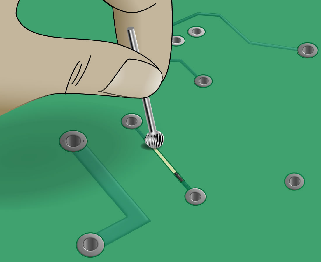
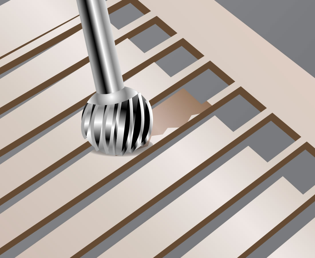
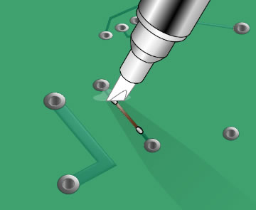
STEP 1: Scrape away resist from repair areas.
|
Scrape away resist. |
The damaged trace should be cut away and removed using a cutting tool, being careful not to damage any surrounding traces, components and contacts. Whenever possible, this repair should be made at least three millimeters away from contacts that will later be soldered in order to minimize the chance of reflowing the repair. Before pulling off the damaged trace, double-check that your cut is complete. Otherwise you risk lifting up the remaining trace and/or contact. Before you can add a jumper, the conductive surfaces must be exposed at the point of the break. You can use the cutting tool to carefully scrape away at least 3mm length of the overcoat material. A rotary tool grinding bit, held in your hand, is a good tool to gently scrape away resist in a controlled way. Make sure to scrape lightly to avoid damaging the conductive material of the trace underneath. Use an alcohol cleaning wipe, solvent cleaning pen, or some other method to remove overcoat particulates and other residues from the repair area. |
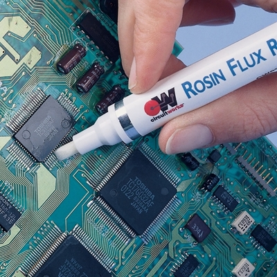
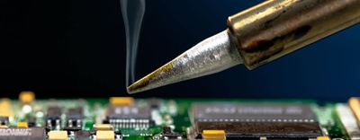
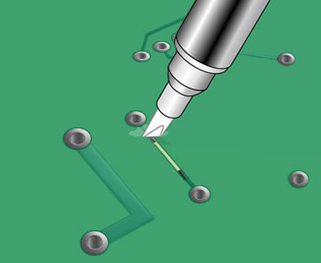
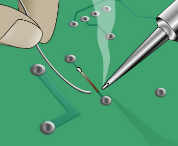
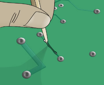
Step 2: Clean and tin exposed contact areas.
|
Clean off resist particulates.
Solder one end of jumper. |
Apply flux to the existing traces, and use a soldering iron and solder wire to tin each end of the trace. Desoldering braid may be used to remove any excess solder. Clean the area again. |
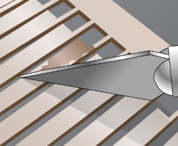
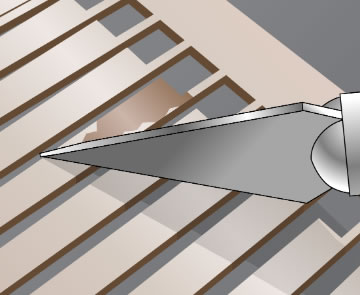
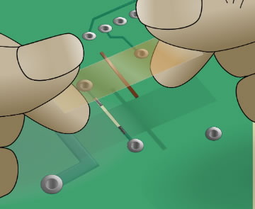
STEP 3: Cut out and prepare foil jumper with adhesive film.
|
Prepare foil jumper.
|
Choose a replacement conductor that most closely matches the original. Conductors are found in various shapes and sizes on sheets called circuit frames. Choose a frame with dry film adhesive backing in order to use this method. The frame can be held against the circuit board to be repaired in order to find the best fitting replacement conductor. This conductor should overlap the conductors on the board by at least two times the width of the conductor. Scrape away the adhesive backing from the part of the foil that will overlap the existing conductor. The same rotary tool as in step 1 can be used to gently scrape the adhesive backing away. Then cut the portion of the foil needed out of the frame by cutting from the non-adhesive side of the frame. Be careful not to handle the adhesive side of the foil. |
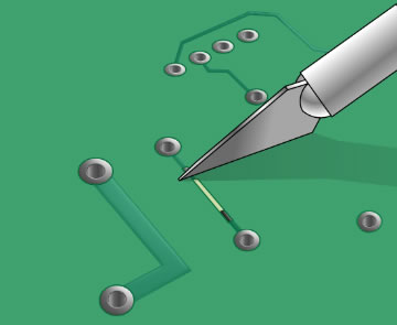
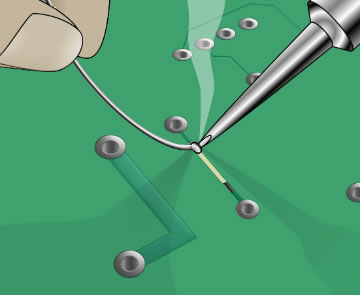
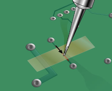
STEP 4: Place new conductor in place using tape.
|
Place new conductor |
Apply flux to the tinned traces on the board. Then overlap one end of the foil over the existing trace by at least twice the width of the trace. Hold the new trace in place using polyamide tape. |
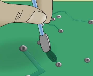
STEP 5: Activate adhesive with bonding tip or soldering tip.
|
Activate adhesive with heated tip. |
Choose a bonding tip or soldering tip that covers the width of the new jumper. Apply pressure onto the tape over the foil using the hot bonding tip or soldering tip. Follow the manufacturer instructions for bonding process. Remove the tape and clean and inspect the area. |
STEP 6: Solder both ends of the foil jumpers to contacts.
|
Solder both ends. |
Use a soldering iron to solder the foil jumper to the traces. The solder that was applied in step 2 is normally enough to make a good connection, so additional solder may not be necessary. |
STEP 7: Clean repair area.
|
Clean repair area. |
Clean the repair area, being careful not to damage the new trace. |
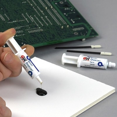
STEP 8: Apply epoxy overcoat.
|
Apply overcoat to repair area.
Spread and texture overcoat. |
Mix the overcoat epoxy according to the manufacturer’s instructions. Apply the epoxy over the trace with a pick. A lint free foam swab can be used as needed to thin and spread the epoxy over the sides of trace. Polyamide tape may be used to mask areas from the epoxy. Alternatively, an overcoat pen can be used to cover and protect the reapired trace as long as the coating will not be exposed to extreme soldering temeratures. The will enable a faster application and cure more quickly. Cure the epoxy or overcoat according to the manufacturer’s instructions. Do not cure at a heat which components on the board cannot tolerate, however. |
Tools & Materials
- Buffer
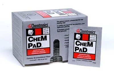
- Cleaner like flux remover pen or alcohol pad
- Adhesive-backed onductor foil jumpers
- Epoxy overcoat
- Overcoat pen
- Polymide tape
- Knife
- Wire solder
- Soldering iron with tips
- Shear cutter
Ask A Technical Question
Stay up-to-date on Chemtronics news, products, videos & more.
Related Products